
Sample — fictional building, not a client project
This page shows how we lay out a filing package, a coordination study and a capacity summary. The building, numbers and equipment are made up. Nothing here was sealed, filed or built.
000 Example Street, New York, NY (fictional address) · Mixed-use, 24 stories (fictional)
Utility service 480Y/277 V, 3-phase, 4-wire · Owner: "Example Owner LLC" (fictional)
Plan review package excerpt
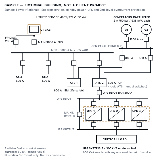
Service kVA per NYC Electrical Code §110.2(C)
| Service disconnect | Amps counted | kVA at 480 V |
|---|---|---|
| MSB main, 3000 A | 3,000 A | 2,494.2 |
| Fire pump disconnect (100 hp, FLA 124 A × 125%) | 155.0 A | 128.9 |
| Total service capacity | 2,623.0 kVA |
kVA = √3 × 480 V × A ÷ 1000. Sample values.
Findings (sample)
- 2,623.0 kVA ≥ 1000 kVA: Electrical Plan Review required (§110.2(B)(1)).
- Service equipment ≥ 2000 kVA: drawings show the room cooling method (1 RCNY §4000-01(b)(1)(iii)(M)).
- Two 938 kVA generators, each under 1000 kVA, within a 1000 kVA-or-larger submission: one-line shows their connection to normal service, frame grounding and neutral bonding (4-pole transfer switches) (§4000-01(b)(1)(iii)(S)). The paralleled plant totals 1876 kVA, so we also show the generator room layout and confirm the approach with the DOB examiner.
- Generator redundancy: sample standby demand is 700 kW, so either generator can carry it alone (N+1). Each transfer switch has its own feeder breaker on the generator paralleling bus (600 A to ATS-1, 800 A to ATS-2), so a fault on one emergency feeder doesn't take out the other.
- Available fault current shown at the service entrance and where interrupting ratings change (§4000-01(b)(1)(iii)(N)).
- UPS system shown as part of the installation (§110.2(B) lists UPS systems): three 300 kVA modules in N+1, so 600 kVA stays available with any one module out of service, plus a maintenance bypass to service the system without dropping the critical load.
- Selective coordination statement on the drawing; PE coordination report filed before inspection, including the ATS-2 to UPS input breaker, the module breakers and the bypass device.
Coordination study excerpt
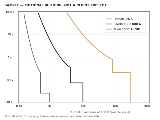
Settings table (sample)
| Device | Rating | Long time | Short time | Instantaneous |
|---|---|---|---|---|
| MSB main | 3000 A LSIG | 1.0 × In, band 4 | 4 × In, 0.3 s | Off |
| DP-1 feeder | 800 A LSI | 1.0 × In, band 3 | 5 × In, 0.2 s | Off |
| Branch | 225 A TM | Fixed | — | Fixed |
Summary of findings (sample)
- Main, feeder and branch curves do not overlap across the available fault range.
- Emergency-system transfer switch feeders coordinated with the generator main.
- One existing feeder device cannot coordinate with its downstream branch; replacement recommended.
Capacity summary
Sample Annex (fictional), a 1960s six-story building on a 1200 A, 208Y/120 V service. The board wants heat pumps, eight EV chargers and electric domestic hot water.
| Item | kVA | Basis (sample) |
|---|---|---|
| Existing service capacity, 1200 A at 208 V | 432 | √3 × 208 V × 1200 A |
| Existing demand | 325 | 12-month peak demand from utility data, plus 25% margin |
| Heat pumps (added) | 180 | Manufacturer data at design heating condition |
| EV chargers, 8 × 7.2 kW, managed (added) | 35 | Load management limit |
| Electric water heating (added) | 45 | Heat pump water heater with backup elements |
| Projected demand | 585 | Exceeds existing service by about 153 kVA |
Options (sample)
- Partial electrification on the existing service. Heat pumps sized for part of the heating load (about 105 kVA), existing boilers kept for peak days, EV charging and water heating deferred. Projected demand about 430 of 432 kVA: it fits, with no margin.
- Upgrade the service to 2000 A at 208 V (about 720 kVA). Covers the full plan. Under 1000 kVA, so §110.2(B) plan review is not triggered. Requires a utility service request and load letter.
- Add a second service. Usually costlier; considered only if the utility can't upgrade the existing one.
Sample values for format only. A real study uses the building's actual demand data and equipment.
What you get, and when
- Task order confirming scope, fixed fee and what DOB will need
- Sealed drawings: one-line, plan view, room layout as required
- Service kVA calculation and fault current values
- EPR intake and cover sheet, filed with DOB
- Objection responses and amendments through approval
- PE selective coordination report before inspection
11business days from a complete submittal package (standard turnaround)
5business days for a complete resubmittal
Want this for a real job?
Send the equipment list and a one-line sketch. We'll confirm the scope and quote a fixed fee.
jstrafer@straferengineering.com
Site visits in all five boroughs and across New York State.